017
IC 4017 – Pin Configuration & Application
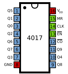
4017 IC
CD 4017 IC-Decade Counter: CD4017 is used for low range counting applications. It can count from zero to ten and its outputs are decoded. The circuit designed by using this ic will save board space and also time required to design the circuit.
Pinout:
the functionality of each pin
cd4017 Pin#
|
Pin name
|
Pin direction
|
Pin purpose
|
1
|
Q5
|
Output
|
It goes high when the counter reads 5 counts
|
2
|
Q1
|
Output
|
It goes high when the counter reads 1 counts
|
3
|
Q0
|
Output
|
It goes high when the counter reads 0 counts
|
4
|
Q2
|
Output
|
It goes high when the counter reads 2 counts
|
5
|
Q6
|
Output
|
It goes high when the counter reads 6 counts
|
6
|
Q7
|
Output
|
It goes high when the counter reads 7 counts
|
7
|
Q3
|
Output
|
It goes high when the counter reads 3 counts
|
8
|
GND
|
Power
|
Ground supply
|
9
|
Q8
|
Output
|
It goes high when the counter reads 8 counts
|
10
|
Q4
|
Output
|
It goes high when the counter reads 4 counts
|
11
|
Q9
|
Output
|
It goes high when the counter reads 9 counts
|
12
|
CO
|
Output
|
This is divided by 10 output which is used to cascade the IC with
another counter
|
13
|
EN
|
Input
|
Enable/Disable:
·
enable (normal mode) -->
connected to ground or logic LOW voltage
·
disable --> connected
to logic HIGH voltage
|
14
|
CLK
|
Input
|
Clock Input: The count advances on the rising edge of the
clock
|
15
|
MR
|
Input
|
Reset:
·
normal operation -->
connected to ground or logic LOW voltage
·
Reset --> connected
to logic HIGH voltage
|
16
|
VDD
|
Power
|
Positive supply
|


Comments
Post a Comment