016

555 Timer
The 555 timer IC is an integrated circuit (chip) used in a variety of timer, pulse generation, and oscillator applications.
designed in 1971
Pinout:
555 Pin#Pin namePin directionPin purpose1GNDPowerGround supply2TRIGInputTrigger3OutOutputOutput: a push-pull (P.P.)· low state (ground supply at GND pin)· high state (positive supply at VCC)4RESETInputReset: a timing interval reset by· driving this pin to GND --> reset· rises above 0.7 Volts --> timing begin again5CONTInputControl: provides access to the internal voltage divider6THERSInputThreshold: when voltage at this pin is > CONT pinthen the timing (OUT high) interval ends7DISCHOutputDischarge: this is an open-collector (O.C.) output, which can be used to discharge a capacitor between intervals, in phase with output.8VCCPowerPositive supply
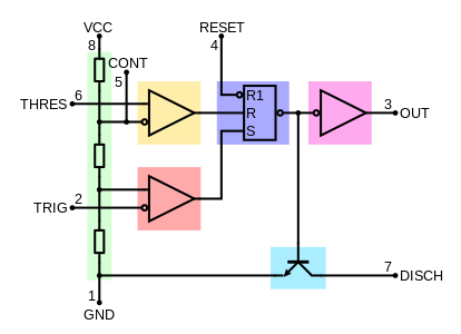
Internal schematic:
- Green: Between the positive supply voltage VCC and the ground GND is a voltage divider consisting of three identical resistors
- Yellow: Comparator
- Red: Comparator
- Purple: An SR flip-flop stores the state of the timer and is controlled by the two comparators.
- Pink: The output of the flip-flop is followed by an output stage with push-pull (P.P.) output drivers that can load the "Output" pin with up to 200 mA (varies by device)
- Cyan: Also, the output of the flip-flop turns on a transistor that connects the "Discharge" pin to ground.


Comments
Post a Comment